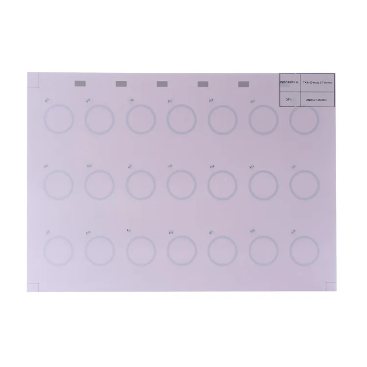
3 × 7 inlay sheet
21 pictured positions
The photo label reads “TK4100 inlay 3*7 format” and “21pcs (1 sheets)”. This identifies the historical pictured example, not the chip supplied on a new order.
Request this layout reference →Components for LF card production
Fixed-ID and writable chip-and-coil sheets
LF card inlays combine a low-frequency chip and a multi-turn coil in a sheet for making 125 kHz identification cards. EM4200 provides factory-programmed identifiers; EM4305 and ATA5577C support writable configurations. Choose the chip and data format your reader accepts, then match the sheet layout to your lamination and punching process.
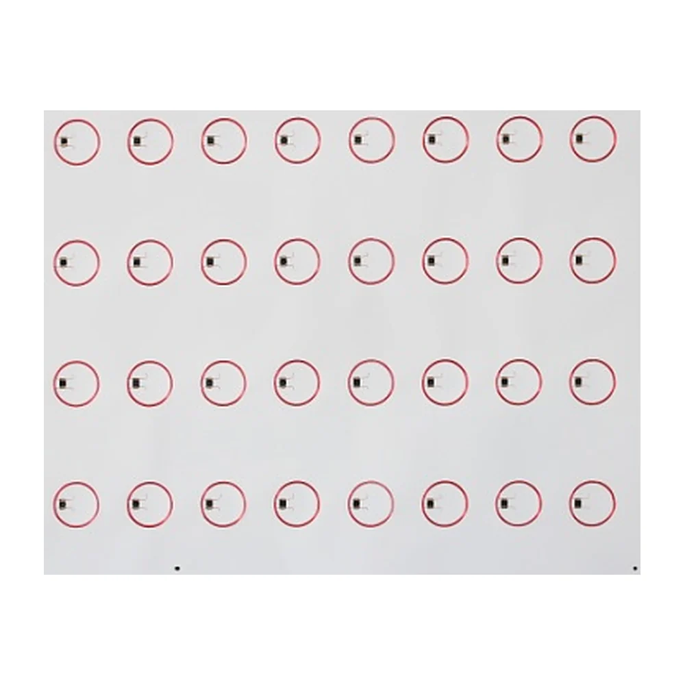
Technical overview
An LF reader needs a matching encoding and identifier format. Coil geometry and the card stack are the next production decisions.
LF chip specifications
Compare the IC capabilities below before specifying a 125 kHz sheet. The quotation identifies the exact chip variant, encoding and supplied coil design.
| Chip | Reader interface | Memory & access | Application fit |
|---|---|---|---|
| EM4200Manufacturer datasheet ↗ | EM4100/4102-compatible options; encoding and bit rate depend on variant | 128-bit ROM; 64 / 96-bit optionsFactory-programmed, read-only. The Manchester 64 version carries 40 data bits within a 64-bit frame. | Fixed-ID cards for a reader accepting the selected EM data format.Request EM4200 quote → |
| EM4305Manufacturer datasheet ↗ | EM4469/4569-compatible commands; Manchester or bi-phase encoding | 512-bit EEPROM · 16 × 32-bit wordsRead/write with protection settings. Includes a factory 32-bit UID, password and configuration; words 5–13 provide 288 user bits for the default message. | Writable identification data with an EM4305-compatible reader/writer.Request EM4305 quote → |
| ATA5577CManufacturer datasheet ↗ | Configurable Manchester, bi-phase, FSK, PSK or NRZ; matching reader settings required | 363-bit EEPROM · 11 × 33-bit blocksRead/write by block. Each block includes one lock bit; configuration and traceability also use memory. | Configurable LF card projects with a defined reader format and encoding file.Request ATA5577C quote → |
ROM and total EEPROM are different quantities. Configuration, identifiers, protection words and lock bits occupy part of the memory shown; the reader may return only part of the transmitted data.
ATA5577C names the documented Microchip family. For a chip described only as “T5577”, provide the manufacturer and exact part number for comparison.
Identifier format example
The EM4200 Manchester 64 variant uses the frame below. A reader can present a formatted value instead of the complete frame, so match its returned number to the number stored in your application.
9 + 40 + 10 + 4 + 1 = 64 bits. This example applies to the EM4200 Manchester 64 version. Source: EM4200 datasheet, page 6 ↗
Labelled sheet examples
These two original photographs show round coils and readable layout labels. The labels document the pictured sheets; a new order needs its own chip, dimensions and tolerances.
21 pictured positions
The photo label reads “TK4100 inlay 3*7 format” and “21pcs (1 sheets)”. This identifies the historical pictured example, not the chip supplied on a new order.
Request this layout reference →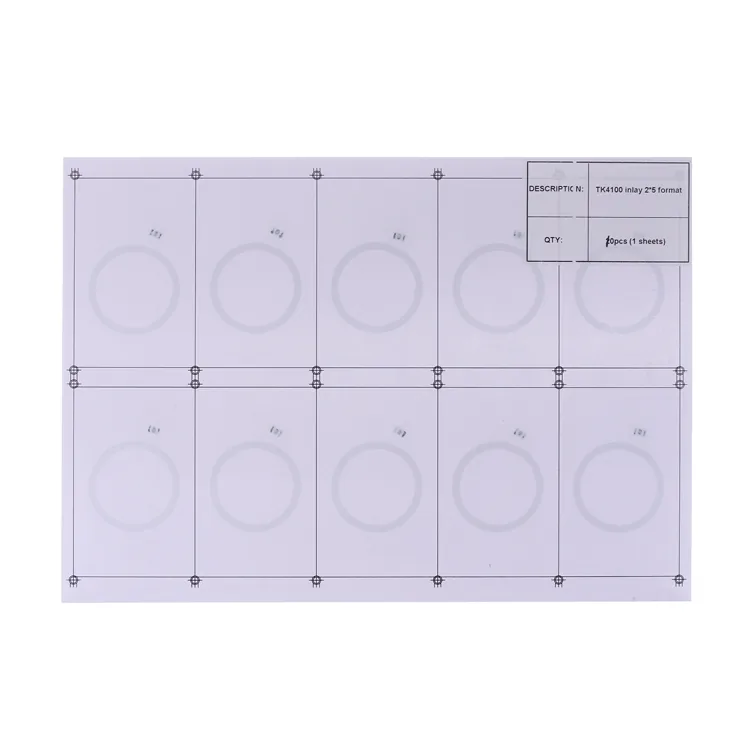
10 pictured positions
The photo label reads “TK4100 inlay 2*5 format” and “10pcs (1 sheets)”. Use this smaller layout as a reference when discussing the production drawing.
Request this layout reference →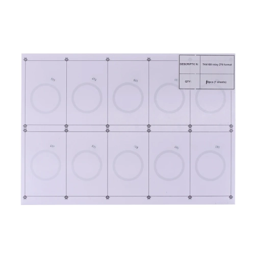
Technical documents
The LF reference brings the chip comparison and photographed layouts into one PDF. The original IC datasheets provide the detailed memory maps and commands.
Download LF technical reference ↓PDF · version 15 September 2026 · technical reference
Custom orders & samples
Choose a chip and pictured layout. On the next page, add your reader model, required identifier format, sheet drawing, quantity and destination.
The quotation will define the supplied chip and configuration, sheet construction, sample charges, MOQ and lead time. Check the reader output on finished sample cards after lamination and punching.
Sample ordering terms →EM4200 uses factory-programmed ROM and is read-only. Map its returned identifier to your card record. If your project needs writable data, compare EM4305 or ATA5577C with the exact reader and writer you use. Those chips need an agreed configuration; writable memory alone does not establish compatibility.
The reader must accept the chip’s encoding, bit rate and data format as well as its operating frequency. For example, the EM4200 Manchester 64 version transmits a 64-bit frame containing 40 data bits. Confirm which value your reader returns and test finished sample cards before approving the order.
A 125 kHz LF inlay does not provide the 13.56 MHz NFC interface used for phone tapping. Select an appropriate HF NFC chip for a phone-link card. A credential intended to work with both an LF reader and NFC needs a combined design containing the relevant chips and antennas.
May we use Google Analytics cookies to measure visits and inquiry actions? Your choice does not affect the contact form. Cookie details