Skip to content

Card production components

UHF RFID Card Inlays

EPC Gen2 chip and antenna sheets

UHF RFID card inlays combine a passive EPC Gen2 chip and antenna for conversion into cards read by a UHF reader. Their EPC memory holds the card identifier; antenna design and the finished card materials determine RF performance. Compare the exact chip memory below and review the sheet examples before requesting a design for your reader region.

Air interface
UHF EPC Gen2
EPC capacity
96 or 128 bits by chip
Supply form
Inlay / prelam sheets
Download technical reference (PDF) ↓
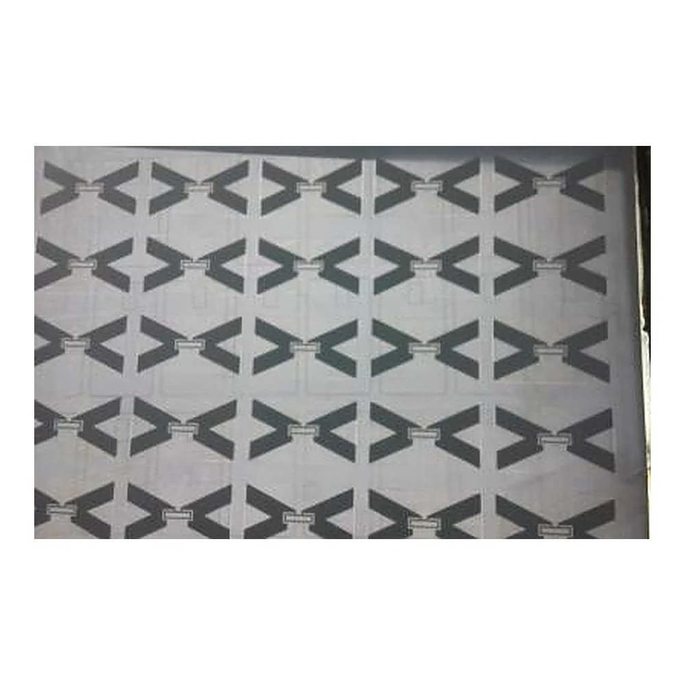
Rows of dark bow-tie antenna patterns on a pale sheet, with partial antennas at its edges.
Bow-tie antenna sheetACT Q4 2017 · slide 18 · historical reference ↗

Technical overview

Select the identifier capacity and the RF design.

The chip holds data. The complete antenna and card assembly must work in the intended reader zone.

Air interface
EPC Gen2 / ISO 18000-63. Required commands and memory access depend on the exact chip.
Chip RF ranges
UCODE 8 / 9: 840–960 MHz IC input.
M730 / Monza R6: 860–960 MHz carrier. These are datasheet chip ranges; the finished antenna and reader configuration must suit the deployment country. How band selection works.
EPC memory
128 bits: UCODE 8 and M730.
96 bits: UCODE 9 and legacy Monza R6.
TID / user memory
All four exact chips have 96-bit TID and 0-bit separate user memory. Compare the memory banks.
Pictured layout
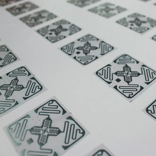
A 3 × 8 / 24-position square-pattern sheet and a cropped bow-tie sheet. These are photo references; the drawing specifies the actual chip, pitch and dimensions.
Production dimensions
Sheet size, substrate, antenna footprint, thickness and punching clearance are defined in the drawing for the selected assembly.

Chip specifications

EPC, TID and user memory are different banks.

Compare the exact IC, including legacy references. These are chip specifications; the quotation identifies the supplied chip, antenna and available sheet construction.

Exact UHF chip memory capacities in bits and application considerations
ChipEPCTIDUserWhat this means for your card
NXP UCODE 8840–960 MHz IC inputManufacturer specs ↗128 bits96 bits0 bits

Card identifiers that need up to 128 EPC bits.

TID is factory-locked and includes a 48-bit serial number. UCODE 8m has a different memory allocation.Keep UCODE 8 distinct from 8m when specifying the EPC length and any extra on-chip data.Request NXP UCODE 8 quote →
NXP UCODE 9840–960 MHz IC inputManufacturer specs ↗96 bits96 bits0 bits

Card systems using a 96-bit EPC identifier.

TID is factory-locked and includes a 48-bit serial number. UCODE 9 is not the extended-memory 9xm.Check the identifier length before substituting this chip into a card design specified for 128 EPC bits.Request NXP UCODE 9 quote →
Impinj M730860–960 MHz carrierManufacturer specs ↗128 bits96 bits0 bits

128-bit EPC card designs using an M730 antenna assembly.

Read-only TID: 32-bit IC identification + 16-bit extended header + 48-bit serialization.M730 and M750 have different EPC/user allocations. Check antenna matching as well as the memory map.Request Impinj M730 quote →
Impinj Monza R6860–960 MHz carrierLegacy / EOL referenceManufacturer specs ↗96 bits96 bits0 bits

Legacy design comparison and replacement planning.

Read-only TID contains IC identification, an extended header and serialization. This is R6, not R6-P.Impinj identifies Monza R6 as in the end-of-life process. Review a supported replacement and requalify the finished card.Review a replacement for Monza R6 →

EPC is the programmable item identifier. TID identifies the IC and is not application storage. All four exact chips shown have no separate user memory; UCODE 8m, UCODE 9xm and Monza R6-P are different variants.

Example: a 128-bit EPC requirement

A reader application requiring the full 128-bit identifier needs an IC with that EPC capacity. UCODE 8 and M730 meet that capacity requirement; UCODE 9 and Monza R6 stop at 96 bits. TID memory cannot be added to EPC memory to make up the difference.

Antenna-sheet examples

Compare the pattern before specifying the sheet.

The full antenna footprint and chip position need to fit inside each finished card. These original photos show actual patterns rather than a generic production illustration.

Rows of dark bow-tie antenna patterns on a pale sheet, with partial antennas at its edges.

Bow-tie antenna sheet

Partial sheet view

Historical photo: ACT Trinnovation Q4 2017, slide 18. Antenna arms and central connection areas are visible; cropped sheet edges prevent a full position count. It does not establish current sheet dimensions or availability.
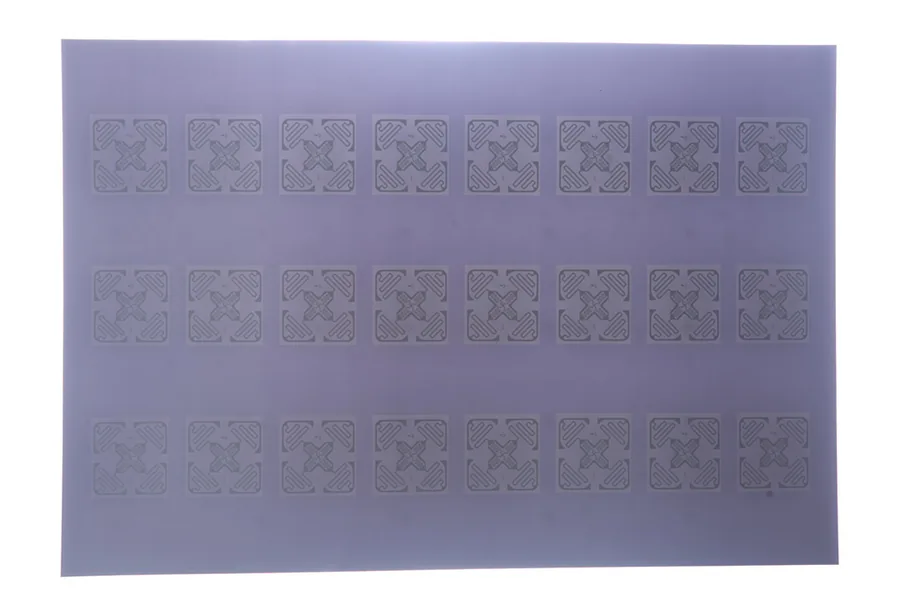
Reference sheet with three rows of eight square antenna patterns, 24 visible positions.

3 × 8 square-pattern sheet

24 pictured positions

A full sheet view from the existing UHF gallery shows 24 positions. The photograph does not identify the chip, antenna size or tuned band; use the approved drawing for those details.

More antenna detail photos
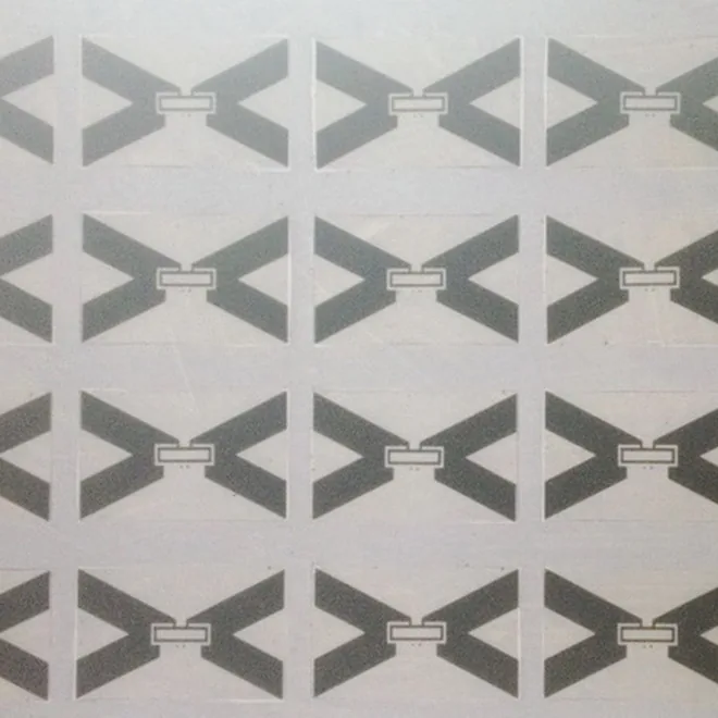
Close-up of bow-tie antenna patterns from the original UHF product gallery.
Bow-tie antenna detail · open full image ↗
Closer view of square antenna patterns from the UHF reference gallery.
Square-pattern detail · open full image ↗

Band & antenna

A wide-band chip still needs the right antenna.

Chip RF specifications describe the IC under stated measurement conditions. They do not certify a particular card for every country or installation.

Match the chip to the antenna

The antenna transforms the incoming RF signal into power for the passive chip. Its geometry and impedance match affect how much power reaches the chip. NXP publishes different impedance conditions for frequency, pad and assembly configurations; exchanging chips needs a design review.

UCODE 9: RF matching reference ↗

Evaluate the finished card in its use position

Card layers, orientation, a hand or holder, and nearby metal can change the RF response. For a parking or personnel card, agree the intended read zone and test the completed sample there. Record the reader, antenna, settings and card position with the result.

Use the country of operation

The reader configuration and antenna band must fit the countries where the cards will be read. For multiple regions, evaluate the proposed design in each intended setup. A shipping destination alone does not identify the RF requirement.

Technical documents

Keep the memory map with the antenna reference.

The PDF brings together the exact-chip comparison, original source links and pictured sheet examples. The production drawing supplies the order-specific dimensions.

Download UHF technical reference ↓

PDF · version 15 September 2026 · technical reference

Custom orders & samples

Request an inlay for your UHF card.

Start with the chip and reader configuration. Add the countries of operation, quantity and your card or sheet drawing on the inquiry page.

The quotation will identify the proposed antenna, chip, dimensions, sample charges, MOQ and lead time.

Sample ordering terms →

UHF inlay questions

Is UCODE 9 a direct replacement for UCODE 8 in every card?

UCODE 9 has 96 bits of EPC memory; UCODE 8 has 128 bits. Both have 96-bit factory-locked TID and no separate user memory. Check the EPC length and required commands, then qualify the proposed chip-and-antenna assembly in the finished card. A shared protocol alone does not make the complete designs interchangeable.

How far will a UHF card made from these inlays read?

A chip datasheet cannot establish the reading distance of a finished card. Antenna geometry, operating band, card layers, reader power, orientation and the holder affect the result. Test the finished sample in its normal use position and record both successful reads and unwanted reads outside the intended zone.

Can a UHF inlay also open a website on an NFC phone?

A UHF-only EPC Gen2 inlay does not provide the 13.56 MHz NFC interface used for phone tapping. A card needing both functions requires an additional compatible HF design or a suitable combined architecture. Evaluate both interfaces in the same completed card.

WhatsAppGet a Quote